


Advanced Search
Search the Knowledgebase


| Author: Microengine Views: 19137 Created: 07-12-2015 04:10 PM | 0 Rating/ Voters |
 |
This article contains the configuration setup for XP-M1000x using Car Park Mode.
Applies To:
- XP-M1000x, XP-M1000ABX, XP-M1300X, XP-M1300ABX, XP-M1000XE, XP-M1000CPX
 Resolution Summary Resolution
Please complete the following steps below:
Wiring Connection
In this section will provide steps to configure wiring connection for Car Park Mode.
For high resolution image, please download the attached wiring diagram at the end of this article.
XP-M1000x to Reader Wiring Connection

| Field | Description | |
|---|---|---|
| XP-M1000x to Reader |
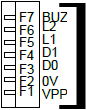 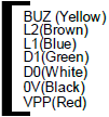 XP-M1000x Entry Reader Exit Reader:  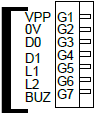 Exit Reader XP-M1000x |
|
| XP-M1000x to Uplink |
If using RS485 Link: Please connect the MCI to the C+ and C- terminal on the controller.  If using RS232 Link: Please connect the RS232 cable to the terminal TX, RX and 0V on the controller. 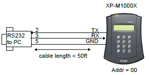 |
|
XP-M1000x to MAS-RBU Wiring Connection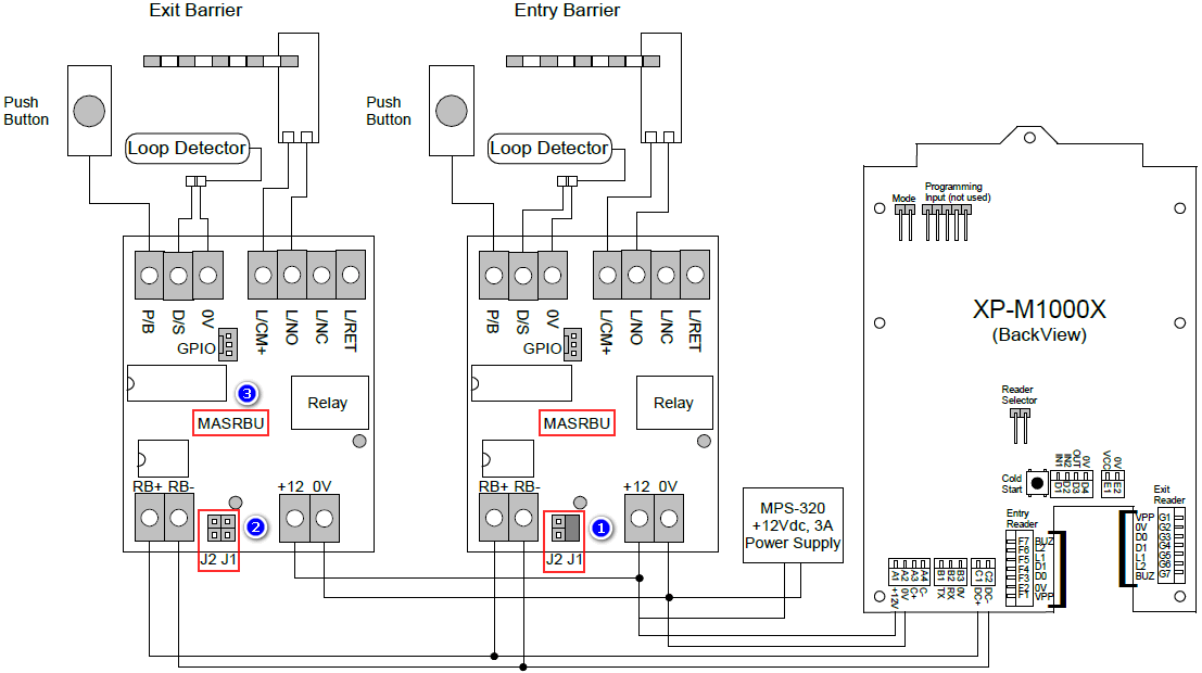
| Field | Description | |
|---|---|---|
| 1 | To set as Entry Barrier, please short/ close jumper J1 on MAS-RBU. | |
| 2 | To set as Exit Barrier, please open jumper J1 and J2 on MAS-RBU. | |
| 3 |
XP-M1000x to MAS-RBU relay board:
MAS-RBU:
|
|
- Power up the controller power.
- Enable the Card Park Mode from the General Parameter Setting on the controller.
- Enter
 Programming Menu.
 - Press '1' for Sys menu.
- Press '6' for General Para. This will bring us to the General Parameter Setting screen.
- Press '0' to toggle between settings until see System Mode menu as shown below.
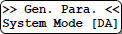
- There are three available modes:-
- DA – Door Access Mode
- CP – Car Park Mode
- TA – Time Attendance Mode
- Press '0' to cycle from one Mode option to another. The default value is 'DA'.
- Please select 'CP' mode. Press '#' to confirm and proceed to next screen.
- Press '#' to confirm saving changes and return to System menu.

- Finished.

Custom Fields
- Summary: This article contains the configuration setup for XP-M1000x using Car Park Mode.
- Search Tags: car park mode, m1000x, how to configure car park mode, how to set barrier, as exit barrier, as entry barrier, wiring connection diagram
Comments
-
There are no comments for this article.
Submit Feedback on this Article
