


Advanced Search
Search the Knowledgebase


| Author: Microengine Views: 34474 Created: 08-06-2015 06:14 PM | 0 Rating/ Voters |
 |
This article contains the wiring connection diagram for XP-M2000i.
Applies To:
- XP-M2000i
 Resolution Summary Resolution
Please follow the following wiring connection diagram.
For high resolution image, please download the attached wiring diagram at the end of this article.
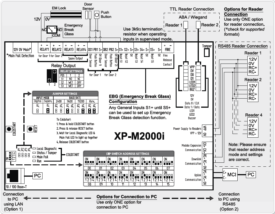
- Configure the wiring connection according to the table below.
- After complete the configuration, run software and configure the software settings.
| Field | Description | |
|---|---|---|
| Power Supply | XP-M2000i to Power Supply
| |
| Field | Description | |
|---|---|---|
| EM Lock | XP-M2000i to EM Lock
| |
| Field | Description | |
|---|---|---|
| Door Sensor | XP-M2000i to Door Sensor
| |
| Field | Description | |
|---|---|---|
| Push Button | XP-M2000i to Push Button
| |
| Field | Description | |
|---|---|---|
| Fire Alarm | XP-M2000i to Fire Alarm (* If connected to the Fire Alarm)
| |
| Field | Description | |
|---|---|---|
| Reader | Connect the reader's terminal:
| |
| Field | Description | |
|---|---|---|
| Uplink | Uplink Connection:
| |
| Field | Description | |
|---|---|---|
| Controller Address | Set the address on XP-M2000i
| |
If user just received controller after repair, please  Coldstart the controller to reset the settings to default.
| Knowledge Management Tool by: KnowledgeBase Manager Pro v6.2.2 (Built with: JS.GUI - AJAX Applications) |

Custom Fields
- Summary: This article contains the wiring connection diagram for XP-M2000i.
- Search Tags: wiring diagram xp-m2000i, drawing, xp-m2000i wiring, wiring connection
Related Articles
Comments
-
There are no comments for this article.
Submit Feedback on this Article
