


Advanced Search
Search the Knowledgebase


| Author: Microengine Views: 50165 Created: 14-05-2015 04:53 PM | 0 Rating/ Voters |
 |
This article contains the wiring connection diagram for XP-SNET.
Applies To:
- XP-SNET
- Extension Board
- Plato Readers
- Reader Interface
 Resolution Summary Resolution
Please complete the following steps.
For high resolution image, please download the attached wiring diagram at the end of this article.
Refer to the following wiring connection diagram: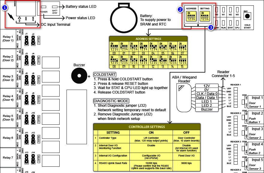
- Connect terminal +12V and GND to Power Supply (12VDC 3A).
- Then short the Main terminal to GND terminal.
- Find ADDRESS from the board.
- Toggle the DIP Switch to set the controller's address (Each address must be unique).
- Follow ADDRESS SETTINGS table (highlighted in yellow) to set the address.This address will be use later when user need to establish communication with software.
- Find SETTING from the board.
- Toggle the DIP Switch to set the controller's setting.
- Follow CONTROLLER SETTINGS table (highlighted in yellow) to set the setting.Controller will be operate according to the Setting configured. Eg: Lift/ Door controller.
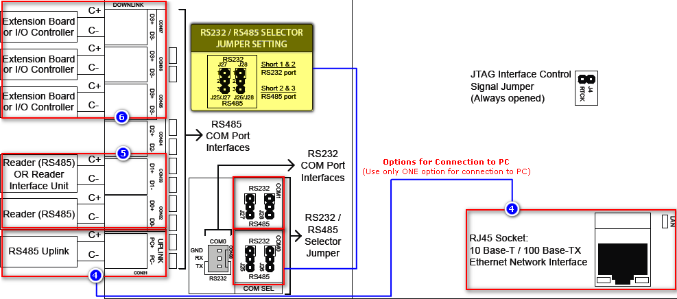
Using MCI (RS485/ RS232)
- Connect terminal C+ and C- from the MCI to the terminal PC+ and PC- from the XP-SNET controller.
- Then short jumper 2 & 3 for RS485 port.
Using LAN
- Plug in the Network/ RJ45 cable to the RJ45 socket on the XP-SNET.
- Make sure the Yellow LED at network socket is blinking upon controller's power up.Configuring the Uplink is to be use when user need to establish communication with the software.
- If not using extension board:
- Connect reader to the terminal CON32 / CON33.
- If using extension board:
- Connect the CON34 / CON35 from the extension board to the terminal CON35 / CON36 / CON37 at XP-SNET controller.
- Then configure the address of the reader (Associate to door). See
 How to configure address setting for XP-SNET reader? (Plato reader/ XP-MK800)Configuring the Downlink is to be use when user need to establish communication with the reader.
- After complete the configuration, please run the software and configure the software settings. If user just received controller after repair, please Coldstart the controller to reset the settings to default.
- Software configuration:
| Business Wiki by: KnowledgeBase Manager Pro v6.2.2 (Built with: JS.GUI - PHP AJAX Framework) |

