


Advanced Search
Search the Knowledgebase


| Author: Microengine Views: 60019 Created: 25-03-2015 05:02 PM | 0 Rating/ Voters |
 |
This article contains the wiring connection diagram for XP-M1000x.
Applies To:
- XP-M1000x, XP-M1000ABX, XP-M1300X, XP-M1300ABX, XP-M1000XE, XP-M1000CPX
 Resolution Summary Resolution
Please complete the following steps below.
Refer to the attached wiring diagram at the end of this article for best view.
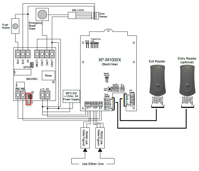
| Field | Connection to MAS-RBU | |
|---|---|---|
| Power Supply | Connect Power Supply (12VDC 3A) to terminal +12V and 0v | |
| EM Lock | Connect to the terminal L/RET and L/NC
| |
| Door Sensor | Connect to the terminal D/S and 0V | |
| Push Button | Connect to the terminal P/B and 0V | |
| Downlink | XP-M1000x to MAS-RBU
| |
Important: Make sure the terminal output from MAS-RBU to lock is producing correct voltage level.
To measure the voltage level at terminal output of MAS-RBU, connect the Multimeter's Red Probe to the L/NC and Black Probe to the L/RET.
1. When door security status is ON, the EM Lock should be in locked condition.
› The voltage measured at terminal L/NC and L/RET showed is about 12V (±10 %)
2. When door security status is OFF, the EM Lock should be in unlocked condition (Door released).
› The voltage measured at terminal L/NC and L/RET approximately +12Vdc (±10 %)
| Field | Description | |
|---|---|---|
| Reader | Connect the entry/ exit reader to the Entry Reader/ Exit Reader terminal at the back of the controller. | |
| Field | Connection to Controller (XP-M100x) | |
|---|---|---|
| Uplink | Using Direct Serial Port: RS232
RS485 (MCI)
| |
- Ensure the jumper J2 is in open condition.
- Please power up the controller after complete the connection.
- Make sure the reader is power ON and connected to a power supply with 12Vdc, 3A.

Custom Fields
- Summary: This article contains the wiring connection diagram for XP-M1000x.
- Search Tags: wiring diagram xp-m1000x, drawing, xp-m1000x wiring
Related Articles
Comments
-
There are no comments for this article.
Submit Feedback on this Article
