


Advanced Search
Search the Knowledgebase


| Author: Microengine Views: 28489 Created: 05-05-2015 03:40 PM | 0 Rating/ Voters |
 |
This article contains the wiring connection diagram for XP-CPRO.
Applies To:
- XP-CPRO
 Resolution Summary Resolution
Please follow the following wiring connection diagram.
For high resolution image, please download the attached wiring diagram at the end of this article.
Controller Wiring Connection Diagram
| Field | Description | |
|---|---|---|
| 1 | Please connect terminal +12V and 0v to Power Supply (12VDC 3A) | |
| 2 |
Uplink Connection:
|
|
| 3 |
Downlink Connection:
|
|
| 4 |
Set the address on XP-CPRO
|
|
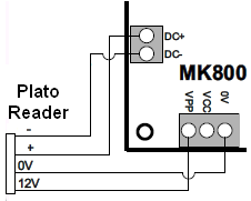
Reader Wiring Connection Diagram
1 Reader Interface (MK800) can be used for 1 door only. Please use other MK800 for the next door.
| Field | Description | |
|---|---|---|
| 1 | Please connect terminal +12V and 0v to Power Supply (12VDC 3A) | |
| 2 | Please connect the RC+ and RC- terminal at XP-CPRO controller to the the terminal C+ and C- from MK | |
| 3 |
Please set the address for the MK (Associated to the Door Unit No).
|
|
| 4 |
Please connect the reader:
|
|
| 5 | Please connect the Push Button, Door Sensor and EM Lock according to the wiring connection. | |
- Please configure the wiring connection according to the table above.
- After complete the configuration, please run software and configure the software settings. If user just received controller after repair, please
 Coldstart the controller to reset the settings to default.
Attachments
 |
mk800-wiring-diagram.pdf | 0.1 Mb | Download File |
| |
xp-cpro-multidoor-controller-wiring-diagram.pdf | 38.7 Kb | Download File |
Custom Fields
- Summary: This article contains the wiring connection diagram for XP-CPRO.
- Search Tags: wiring diagram xp-cpro, mk800, drawing, xp-cpro wiring, xp-mk800, mk800, mk-800, mk, wiring connection
Comments
-
There are no comments for this article.
Submit Feedback on this Article
